Circuit Diagram Of Vfd Drives
Circuit drive frequency vfd diagram variable power simple Motor control circuit diagram taking into account bearing in mind plc Vfd variable speed motor drive ac diagram installation block terminals output off control circuit frequency connected function phase drives controller
VFD On/Off Output terminals
Variable frequency drive What is variable frequency drive circuit: its operation, types and Vfd on/off output terminals
Vfd frequency variable igbt inverter basics wiring cooling hvac
Selecting the proper variable frequency drive (vfd) for applicationsVariable frequency drives explained Vfd variable frequency selectingVfd plc wiring hmi instrumentationtools electrical.
Vfd circuit drive types operation working sourav gupta jan .

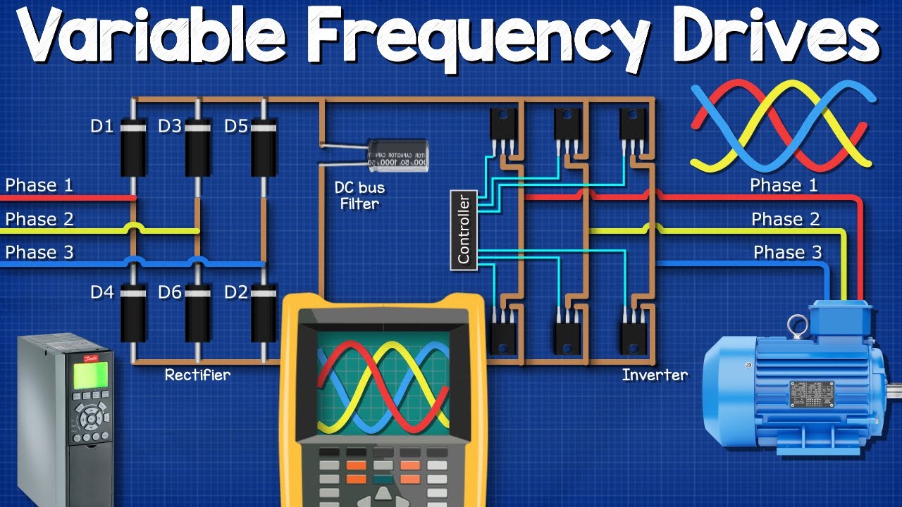
Variable Frequency Drives Explained - VFD Basics IGBT inverter - YouTube

Motor Control Circuit Diagram Taking Into Account Bearing In Mind Plc

Variable Frequency Drive

What is Variable Frequency Drive Circuit: Its Operation, Types and

Selecting the proper Variable Frequency Drive (VFD) for applications | EEP
